In the previous article, the main part of the SATA protocol was analyzed. It consists of four layers: the physical layer, the link layer, the transport layer and the application layer. The data passes through the four layers in turn during the transmission process, and the electrical signal is completed. Conversion of logical data. So how do you deal with the data in each layer? The technical details of each layer are described in detail below.
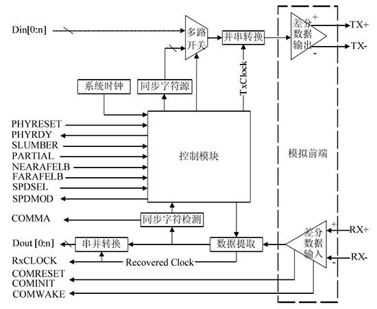
First look at the physical layer, the SATA protocol specifies that the physical layer can transmit parallel data streams to the upper link layer, and receive high-speed (1.5Gb/s, 3Gb/s, 6Gb/s) serial data streams, while simultaneously performing data strings. And conversion, through the transmission and reception of the out-of-band signal to detect the state of the device, to achieve the hot plug function of the interface. The main task of the SATA physical layer is to complete the conversion between serial and parallel data, and drive the digital logic signal into a differential physical signal, sample the received data to obtain the corresponding clock signal, and complete the power-on initialization process of the device through the out-of-band signal. The physical layer interface logic diagram is shown in Figure 1:

Figure 1 SATA physical layer interface logic
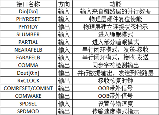
The control module controls the function implementation of the entire physical layer through logic circuits, and is responsible for processing and receiving control signals from the link layer, and feeding back the working information of the layer to the link layer. The analog front end provides the basic interface to the data cable, which includes high-speed serial differential drivers and receivers, as well as OOB signal processing circuitry. The data extraction module is responsible for extracting clock information and data from the input data stream. Synchronous Character Detection and Synchronous Character Source Two modules are responsible for serial/parallel synchronous conversion. The parallel-to-serial conversion module is responsible for converting parallel data received from the link layer into serial data to accommodate serial data transmission of the physical interface. The serial-to-parallel conversion module is responsible for converting host serial data forwarded by the received physical interface into parallel data to accommodate parallel data transmission at the link layer. The logical function description is shown in the table below.
Table 1 SATA physical layer interface logic function description:

When the SATA physical layer interface performs data transmission, the necessary clock signal is not provided in the serial data transmission link, and the physical layer data receiving module has no reference clock signal when detecting the high and low levels of the received data. To solve this problem, the SATA protocol specifies that the data transmission uses the 8b/10b encoding mechanism to provide data detection clock signals to the physical layer receivers using data redundancy information. In addition, in order to enhance the scalability and responsiveness of SATA interface devices, the protocol also defines a special signal: Out Of Band to assist the physical layer to perform power-on initialization and reset operations.
Before the communication link is established on the SATA standard interface, the two ends of the link do not know the communication mode and rate of the other party. Therefore, the transmission information on the signal line cannot be correctly obtained, resulting in failure to communicate normally. Therefore, a special mechanism is needed to ensure that the two parties establish a reliable connection. The SATA 2.0 standard protocol uses the OOB signaling mechanism. The OOB signal is only used to establish communication link, system restart and power management during physical layer initialization. It does not have any effect during normal communication, so it is only an out-of-band signal, ie OOB (Out), compared to normal data stream. Of Band) signal. Differential signal transmission uses a signal strength difference of a pair of signal lines coupled to each other to represent a logical "0" or "1". Taking the SATA standard interface as an example, when the TX (+) is 250m V and the TX (-) is 0m V, TX represents logic "1"; otherwise, it represents logic "0". When TX(+) and TX(-) remain unchanged, both are 250m V, which represents the bus idle state. The OOB signal is just a data short pulse sequence transmission mode initiated when the bus is idle. The peak-to-peak value of the data short pulse sequence is generally within 50m V, which is far lower than the amplitude of normal data transmission. The SATA 2.0 standard protocol defines a total of three OOB signals: COMRESET, COMINIT, and COMWAKE. They are each composed of a set of data bursts with a fixed time requirement and a period of idle time, and are distinguished by the length of the idle time.
(1) COMRESET
COMRESET is only sent by the SATA host for power-on reset and forced restart in error state. COMRESET consists of 160 short bursts of UIOOB (106.7ns) and 480 UIOOB idle states (320ns), as shown in Figure 2. UIOOB is the time unit of the OOB signal, and 160 UIOOB is equivalent to the time taken to transmit 4 DWs. The short pulse can be 4 GEN1 ALIGNP primitives or 4 GEN1 DWs (each DW consists of 4 D24.3 characters).
(2) COMINIT
COMINIT is only sent by the SATA device side and is used to respond to the COMRESET signal on the host side, indicating that the device is ready. The signal format of COMINIT is exactly the same as COMRESET, as shown in Figure 2.

Figure 2 COMRESET and COMINIT signal formats
(3) COMWAKE
COMWAKE can be sent by the SATA host or by the SATA device to wake up the other party. COMWAKE consists of 160 UIOOB short pulses (106.7ns) and 160 UIOOB idle states (106.7ns), as shown in Figure 3.

Figure 3 COMWAKE signal format
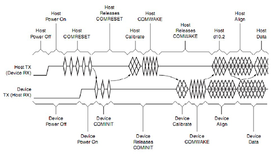
After the physical layer of the SATA interface is powered on and the hardware reset is successful, the host uses the OOB signal to initiate the reset sequence after power-on. After the interface communication is adjusted by a series of self-states such as impedance calibration and self-diagnosis, the host informs the SATA interface device that it is ready, and establishes a reliable and efficient communication link at both ends after speed negotiation and clock recovery. The initialization timing is as follows:

Figure 4 physical layer initialization timing
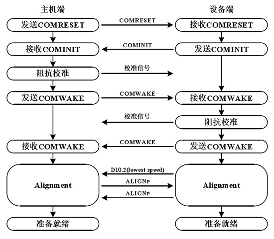
The physical layer initialization process can be divided into two steps: 1. Checking whether the connected device exists; 2. Negotiating the highest transmission rate supported by both ports. The first step is done through OOB signal interaction. Both ports send a fixed format signal and then wait for the other party to respond. If a response is detected, the device already exists and a second step can be taken. Both ports send a stable data stream in a fixed format. The SATA device end negotiates the highest transmission rate supported by both parties by continuously decelerating, and extracts the clock signal from the data stream to achieve data synchronization. At this point, both ports can communicate normally. The specific process is:

Figure 5 initialization process
After the hardware is powered on, the Host starts to reset and continuously sends a COMRESET signal to the Device during the reset. After the Host side reset is completed, stop sending the COMRESET signal to the Device and wait for the response from the Device.
After receiving the COMRESET signal, the Device will reset it. After the reset is completed, it will respond to the Host by sending a COMINIT signal, indicating that the Device is ready to go to the next stage.
If the Device does not successfully receive the COMRESET signal before the Host stops transmitting the COMRESET signal, the COMINIT response signal cannot be sent. The Host waits for 10ms and then times out. It needs to be reset again. If the COMINIT response signal is sent after the Device is ready, the Host Still in the reset state, the Device will enter the reset again and send a COMINIT response signal until the Host reset is complete.
When the Host detects the COMINIT response signal from the Device, it enters the impedance calibration state. The Host side uses the transmission cable as a reference for the current signal transmission environment, uses the TDR test scheme for self-diagnosis and makes some appropriate adjustments to the high-speed differential signal transceiver to achieve the best signal quality. The adjustment of the high-speed differential signal transceiver is mainly to match its internal impedance, reduce signal loss and ensure signal integrity. It should be noted that impedance calibration is not required for the physical layer initialization process and is chosen as appropriate.
After the impedance calibration is completed, the Host sends a COMWAKE signal to the Device and waits for a response. At this time, after receiving the COMWAKE signal, the Device side performs clock calibration, and can also perform impedance calibration and notify the Host to enter the rate negotiation phase by COMWAKE signal.
In the rate negotiation phase, the Device side dominates the process, and the Host side only responds. After the Device sends the COMWAKE signal to the Host, it sends the ALIGNP sequence to the Host continuously at the maximum rate it can support. If the device does not detect the ALIGNP sequence replied by the host after 54.6us, the device determines that the host does not support the transmission rate. The device automatically reduces the rate to the next level and repeats the above process. If it is minimized and the Host still does not respond, it enters an error state.
After receiving the COMWAKE signal sent from the Device, the Host sends the D10.2 character at the lowest rate. At the same time, the Host side will lock the ALIGNP sequence within 54.6us. Once the ALIGNP sequence is locked, it will reply to the ALIGNP sequence at the same rate to support the transmission rate. If the host does not receive the ALIGNP signal in 880us, it will restart the power-on initialization operation and repeat until the application layer forces it to terminate.
The Device side locks the ALIGNP sequence and sends a SYNCP sequence when it is ready to indicate that normal communication can begin. After the host receives three non-ALIGNP sequences, the communication link is established successfully, and the physical layer initialization process ends and enters the normal working state.
In general, the initialization of the physical layer, including the reset phase, the optional impedance matching phase, and the rate calibration phase, all of which require the execution of the OOB signal instruction, which is performed by the Host host and the Device device.
The physical layer of the SATA protocol is basically analyzed, and it seems to be much more complicated than the PATA protocol. These functions are essential for high-speed serial transmission. In the next article, we will continue to introduce the technical principles and details of the other layers of the SATA protocol, so stay tuned.
About Darth Technology
Darth Technology, a national high-tech enterprise, the only collaboration unit for the data recovery of the confidentiality of the Tianjin State Secrecy Bureau, the famous brand in the data recovery industry, leading the data recovery technology in China and even in Asia!
Darth Technology China data recovery and forensics really experts!
More data recovery and forensics cutting-edge technology, please pay attention to WeChat public account: woocs
Micro signal: woocs

Long press to identify the QR code
Focus on data recovery and forensics technology, the Internet
Submission:
Hand pump sprayer's working pressure is from 2 to 8pa , it has a capacity of 1L / 1.5L / 2L / 3L,the material is PE and different color can be offer.It's very convenience to be used. It has high corrosion resistant and durable . Front switch is more easy to control , it can be used for gardens , parks , botanical gardens , etc . there's an exhaust valve in it , When the pressure is out of range , it can protect your safety . Also the effect of fog water is very good , it can also be spray straight line . Meanwhile the size of the atomization can be mediated , Hand pump sprayer has better quality and better drainage . We have many advantages over other products , first of all , we are very stricted in controling over the raw materials , sencondly , we have more than 20 years experience in mold translation . thirdly , we will carry out a complete inspection of each product , we have a complete set of testing equipment to ensure that each product to the hands of customers have no quality problems . Hand pump sprayer has already been the daily tool for people to make plants better . Hand pump sprayer can also used on routine disinfection . It will help your daily life more convenience , more safe .
Hand Pump Sprayer,Hand Held Pump Sprayer,High Pressure Hand Pump Sprayer,Hand Pump Water Sprayer
YUYAO ZHENGYU SPRAYER FACTORY , https://www.zysprayer.com